
Last year, some friends and I visited Mechanicon, the largest keyboard convention in Europe. Here, enthusiasts can present their creations and vendors can offer their items, with a prize raffle concluding the event. Sadly (or perhaps luckily, given that I didn’t need something) I didn’t win anything, however I did manage to pick up some low-profile switches from the trade corner. Once I had some switches in hand, I knew what I wanted to do: create my own PCB and keyboard. A numpad, to be precise. Since I have time to design my PCB and learn new things, how hard could it be?
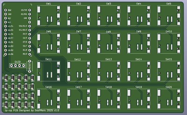
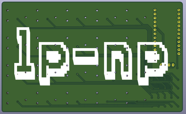
When I got home, I fired up KiCAD. I started by looking at my past experience of building a split keyboard, the Corne. I used a finalized PCB layout for that project, which I built back in 2020. My design would be simpler, but would share the same electrical components, such as the controller and diodes. I simply had to design the circuit layout to allow for a numpad. The next stage was designing the PCB itself. The tricky part was figuring out how to transfer the footprint from the circuit design to the PCB layout. I used the Corne reference for most of the elements and found a proper footprint library for the low-profile switches on GitHub. Note, for this project I use the Cherry MX ULP switches. There are the Kailh PG1316S switches, which are similar but have a different footprint. Then it was time to draw the traces. For this, I used educated guesswork and the default settings. With the help of friends who had some PCB design experience, I was able to finalize my design. I only used the Corne design as a starting point. All I needed to do was research how to create a copper fill for the void spaces on the PCB. It’s amazing how simple open-source software can be for such a complex task.
After the review was complete, I slept on it for a night to avoid any obvious flaws. For the test fit, I printed the board out on paper, after which the design was ready to order. As the manufacturer, I selected the same fabrication service that I had used for the Corne PCBs, as the quality/price ratio was good. When ordering, I selected the stencil option, as the soldering pads would be quite small, especially for the diode matrix in the bottom left corner of the previous picture.
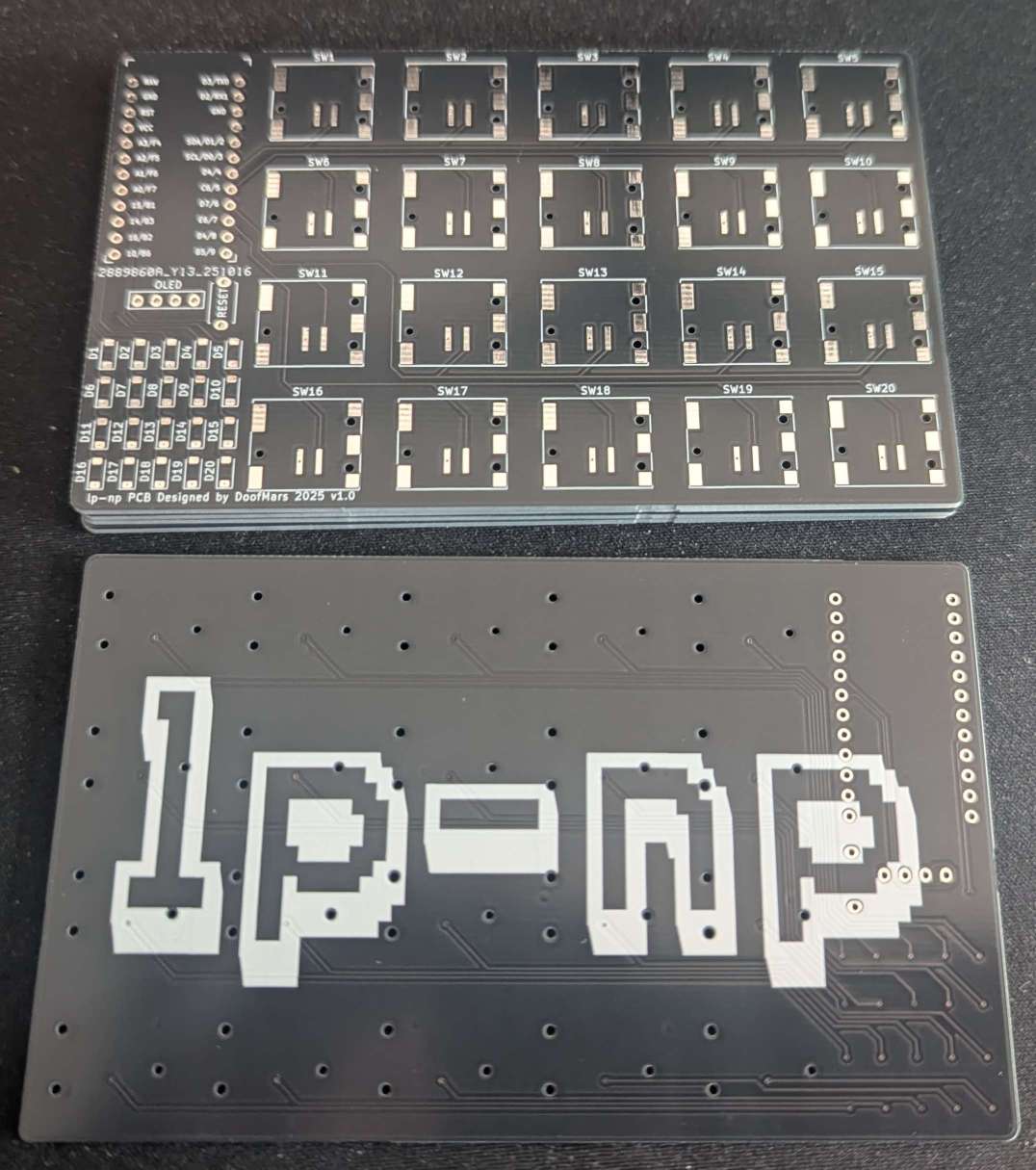
Next time I order a stencil, I must remember to specify the dimensions, as the package I received was quite large. I don’t need such a large sheet of metal for my small PCB. On the subject of the package, the PCB arrived on time. Due to the process, I had to order five pieces. I can give these away at the next keyboard event.
I had to order other parts besides the switches for the components. Mainly a controller board. For the Corne, I used a Pro Micro with an Atmega 32u4 microcontroller and a small LCD screen. I already had the required diodes lying around from a past project. To solder with the stencil, I ordered a hot plate and solder paste. The former did not arrive in time. However, I was able to finish the assembly by borrowing an infrared soldering iron from a friend.
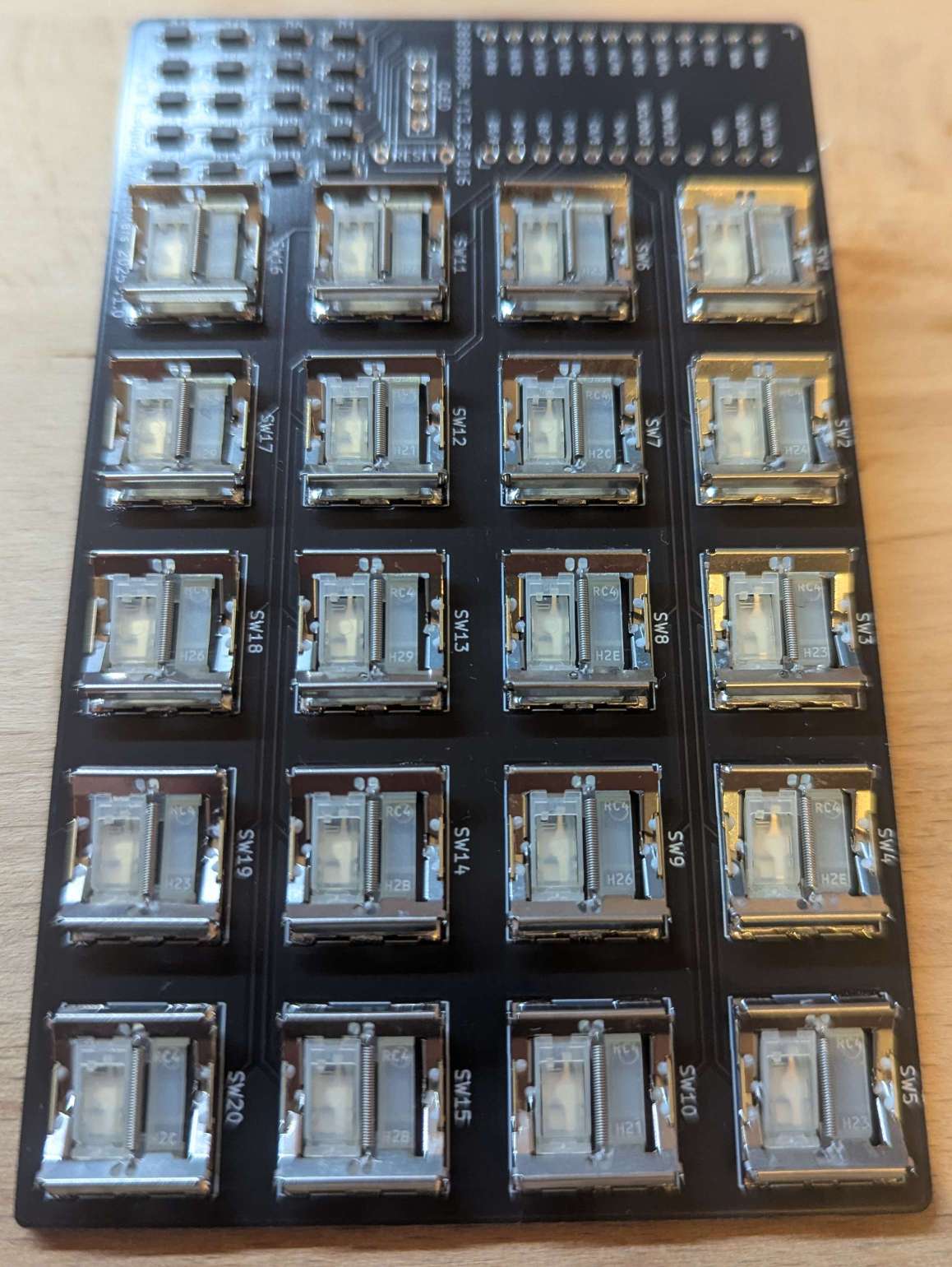
The initial experience of working with a stencil was not complex. However, a smaller sheet or jig to align the stencil with the PCB would be helpful next time. Using an old credit card and my gloved fingers to apply the paste ensured an even spread in every cut-out of the stencil. After confirming that every hole was sufficiently filled, I carefully removed the PCB from the stencil. The next step was to place the components on the board. Once everything was in place, I used the preheated oven to melt the solder paste around the solder pads of the SMD components. Thankfully, I had done a test run to ensure the right temperature profile. Otherwise, I would have risked a poor solder connection and extra work. I only had enough switches for one assembly, so any error would have been catastrophic. Placing the switches was easy, but the very small diodes required more care.
Once the heat profile had finished, I allowed the PCB to cool down. Then it was time to solder in the final components manually and perform some tests and measurements to check that the connections were working as expected. Fortunately, I had made no design or assembly errors and everything worked.
The next task was to program the microcontroller. For this, I used the QMK firmware. It’s the same firmware that I used for the Corne keyboard. After browsing the directory of available keyboard configurations, I found a similar configuration with 4×5 switches arranged in a simple row/column setup. To get this setup to work with my board, I just had to make some minor adjustments. The rows and columns were arranged differently to mine. However, the QMK firmware can be configured accordingly. Finally, the keyboard worked with every configured key.
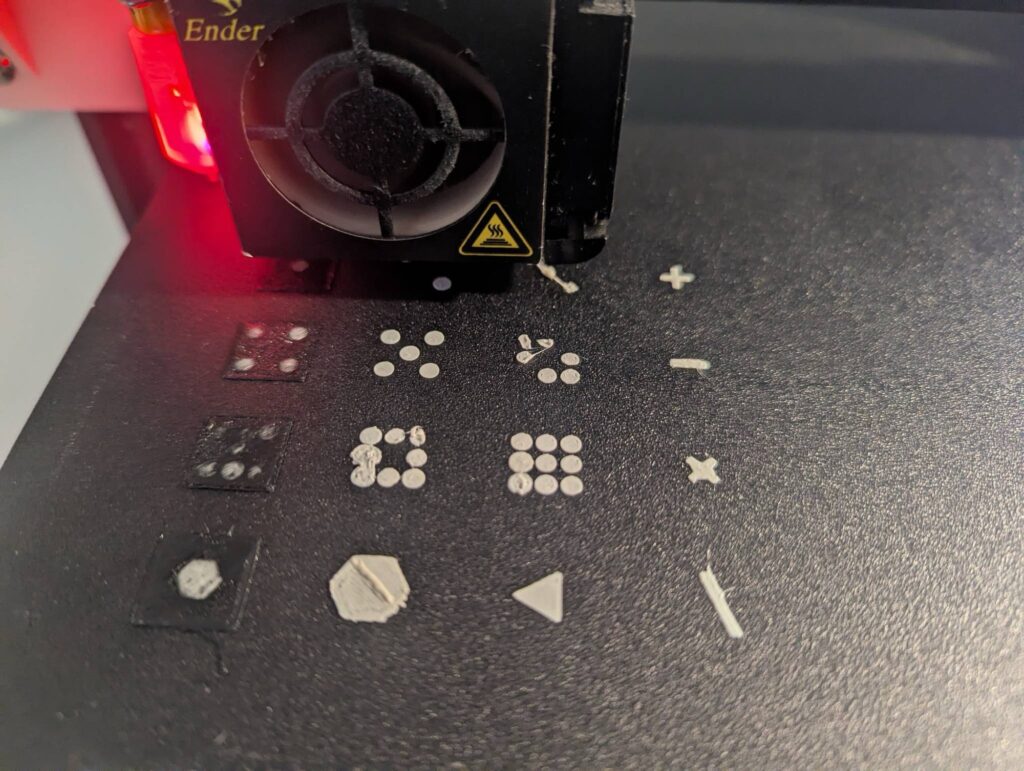
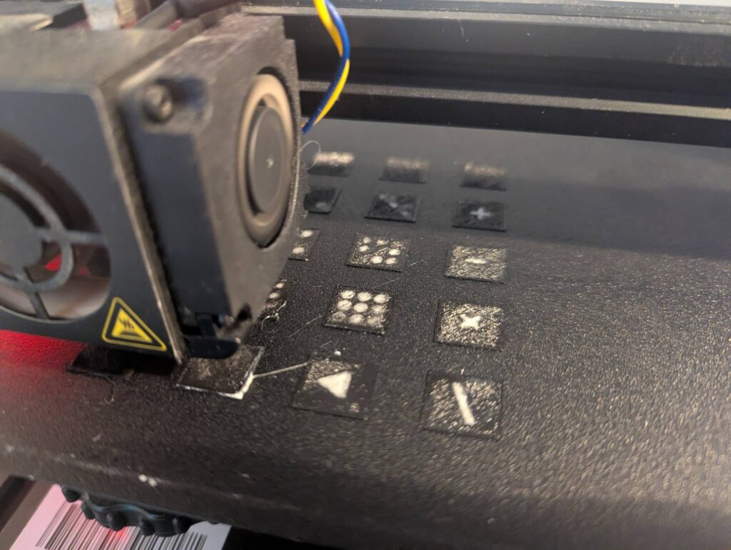
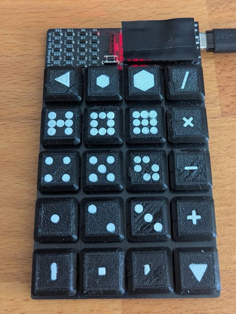
The final task is to design and print the key caps. As the switches do not have a standard layout, it is difficult to find suitable keycaps, so I had to resort to 3D printing my own. I found some 3D objects of modeled keycaps for a different project by mikeholscher, and after making some adjustments, I was able to remove the top curvature of the keycaps. I then printed the caps face down and used the print plate to print the labels first. I used simple shapes to design the labels. I used dots for the numbers, triangles for backspace or delete, mathematical symbols for mathematical functions, and two hexagons of different sizes for volume.
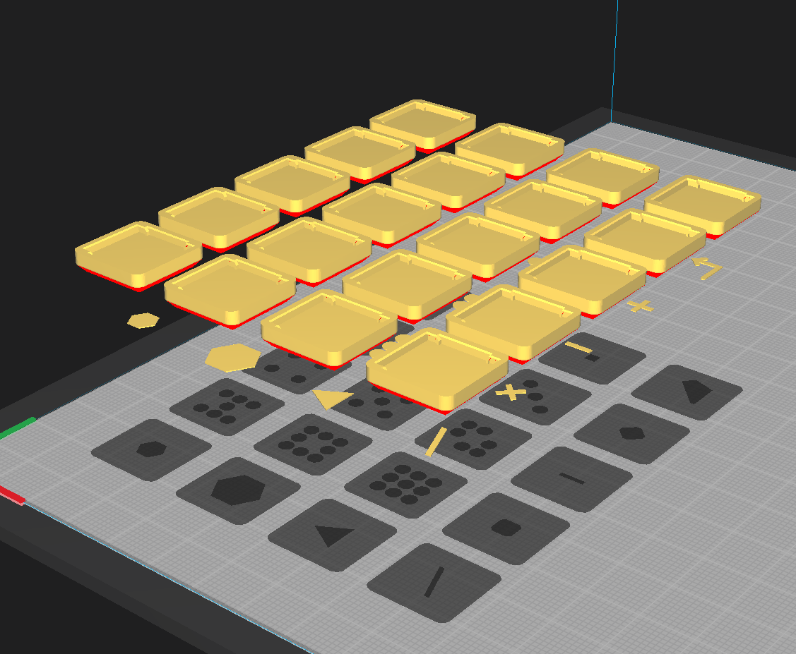
I printed the label first in white and then used black for the main body. This turned out to be somewhat problematic as the plastic would sometimes not stick properly to the print surface. To print a new batch, the color had to be changed from black to white. This required purging the leftover black filament. Otherwise, the print would be dull gray. After several trial and error attempts, I managed to print a decent set of caps.
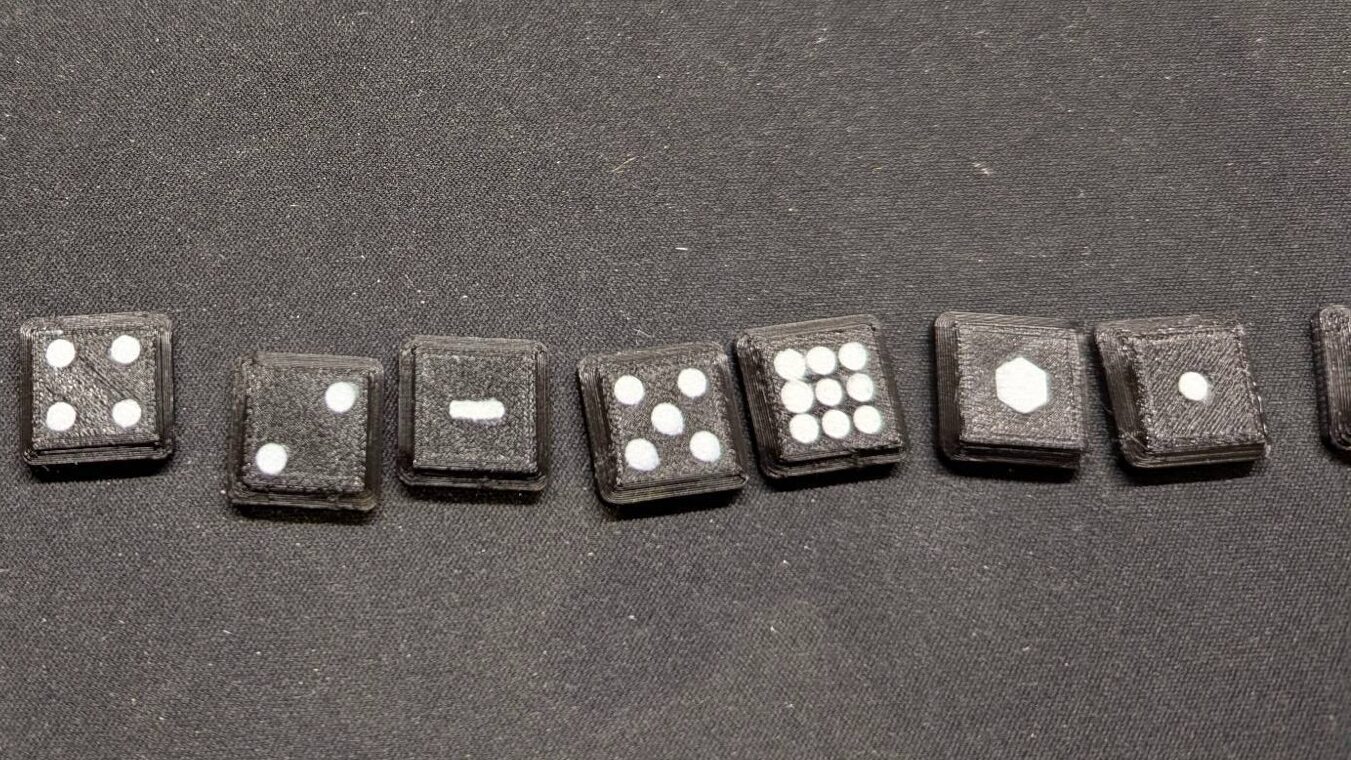
In conclusion: This project presented a great opportunity to build my first device involving a custom PCB from scratch. Building based on the Corne helped, but there are other other good resources out there that I could have used. The keyboard or numpad is extremely slim at only 8 mm in height. Next time, I will try to avoid fragile, low-profile scissor switches as they can break quickly if the cap does not fit properly.
The project is available on GitHub and I try to get my layout published to the QMK firmware.
Bill of Materials (BOM)
| Reference | Component Description | Value | Amount |
|---|---|---|---|
| U | ProMicro (or compatible derivate) | 1 | |
| U-Header | Generic connector, single row, | Conn_01x12 | 2 |
| J | Generic connector, single row, 01×04 | Conn_01x04 | 1 |
| RSW1 | Momentary Tact Tactile Push Button Switch 2 Pin DIP | 3×6 | 1 |
| OLED | Mini 0.91 Inch 128×32 OLED | Optional | 1 |
| D | Diode (SOD-123) | D | 20 |
| SW | Cherry MX ULP (Ultra Low Profile) Switches | SW_Push | 20 |